Exercise – 3 / Editing map features & Attribute Management
Vector data layers can be edited within QGIS Desktop. Editing allows to add, delete and modify features in vector data sets.
- The first step is to put the data set into edit mode.
- Select the layer in the Layers panel and click Layer→Toggle Editing.
- Multiple layers can be edited at a time. The layer currently being edited is the one selected in the Layers panel.
- Once in edit mode the Digitizing Toolbar can be used to add, delete and modify features.
- Activate Digitizing toolbar(See Figure 9 Digitizing toolbar)
- To activate Digitizing toolbar, right click on the toolbar menu and select AdvanceDigitizing toolbar.

Figure 28- Activate Advance Digitizing toolbar
Note: Based on the features (Line/Point/Polygon) editing tools will be highlighted.
Figure 29 - Advance Digitizing toolbar for Line feature
Figure 30 - Advance Digitizing toolbar for Point feature
Figure 31 - Advance Digitizing toolbar for Polygon feature
From left to right the tools are:
- Enable Advanced Digitizing Tools
- Copy & Move Features
- Rotate Features
- Simplify Features
- Add Ring
- Add Part
- Fill Ring
- Delete Ring
- Delete Part
- Reshape Features
- Offset Curve
- Reverse Line
- Trim/Extend Features
- Split Features
- Split Parts
- Merge Selected Features
- Merge attributes of Selected Features
- Rotate Point Symbols
Use Rotate Feature(s) to rotate one or multiple features in the map canvas. Press the Rotate Feature(s) icon and then click on the feature to rotate. Either click on the map to place the rotated feature or enter an angle in the user input widget. If you want to rotate several features, they shall be selected first.
If you enable the map tool with feature(s) selected, its (their) centroid appears and will be the rotation anchor point. If you want to move the anchor point, hold the Ctrl button and click on the map to place it.
If you hold Shift before clicking on the map, the rotation will be done in 45-degree steps, which can be modified afterwards in the user input widget.
To abort feature rotation, you need to click on Rotate Feature(s) icon.
The Simplify Feature tool allows you to reduce the number of vertices of a feature, as long as the geometry remains valid. With the tool you can also simplify many features at once or multi-part features.
First, click on the feature or drag a rectangle over the features. A dialog where you can define a tolerance in map units, layer units or pixels pops up and a colored and simplified copy of the feature(s), using the given tolerance, appears over them. QGIS calculates the amount of vertices that can be deleted while maintaining the geometry. The higher the tolerance is the more vertices can be deleted. When the expected geometry fits your needs just click the [OK] button. The tolerance you used will be saved when leaving a project or when leaving an edit session. So you can go back to the same tolerance the next time when simplifying a feature.
To abort feature simplification, you need to click on Simplify Feature icon.
Add PartYou can Add Part to a selected feature generating a multipoint, multiline or multipolygon feature. The new part must be digitized outside the existing one which should be selected beforehand.
The Add Part can also be used to add a geometry to a geometryless feature. First, select the feature in the attribute table and digitize the new geometry with the Add Part tool.
Delete PartThe Delete Part tool allows you to delete parts from multifeatures (e.g., to delete polygons from a multi-polygon feature). This tool works with all multi-part geometries: point, line and polygon. Furthermore, it can be used to totally remove the geometric component of a feature. To delete a part, simply click within the target part.
Add RingYou can create ring polygons using the Add Ring icon in the toolbar. This means that inside an existing area, it is possible to digitize further polygons that will occur as a ‘hole’, so only the area between the boundaries of the outer and inner polygons remains as a ring polygon.
Fill RingYou can use the Fill Ring function to add a ring to a polygon and add a new feature to the layer at the same time. Using this tool, you simply have to digitize a polygon within an existing one. Thus, you need not first use the Add Ring icon and then the Add feature function anymore.
Delete RingThe Delete Ring tool allows you to delete rings within an existing polygon, by clicking inside the hole. This tool only works with polygon and multi-polygon features. It doesn’t change anything when it is used on the outer ring of the polygon.
Reshape FeaturesYou can reshape line and polygon features using the Reshape Features tool on the toolbar. For lines, it replaces the line part from the first to the last intersection with the original line.

Figure 32 - Reshape Line Features
For polygons, it will reshape the polygon’s boundary. For it to work, the reshape tool’s line must cross the polygon’s boundary at least twice. To draw the line, click on the map canvas to add vertexes. To finish it, just right-click. Like with the lines, only the segment between the first and the last intersections is considered. The reshape line’s segments that are inside the polygon will result in cropping it, where the ones outside the polygon will extend it.

Figure 33 - Reshape polygon features
With polygons, reshaping can sometimes lead to unintended results. It is mainly useful to replace smaller parts of a polygon, not for major overhauls, and the reshape line is not allowed to cross several polygon rings, as this would generate an invalid polygon.
Reverse LineChanging the direction of a line geometry can be useful for cartographical purposes or when preparing for network analysis.
To change a line direction:
Activate the reverse line tool by clicking Reverse line.
Click on the line. The direction of the line is reversed.
Trim/Extend FeatureWhen a digitized line is too short or too long to snap to another line (missing or crossing the line), it is necessary to be able to extend or shorten the segment.
The Trim/Extend tool allows you to also modify (multi)lines AND (multi)polygons. Moreover, it is not necessarily the end of the lines that is concerned; any segment of a geometry can be modified.
The tool asks you to select a limit (a segment) with respect to which another segment will be extended or trimmed. Unlike the vertex tool, a check is performed to modify only the layer being edited.
When both segments are in 3D, the tool performs an interpolation on the limit segment to get the Z value.
In the case of a trim, you must select the part that will be shortened by clicking on it.
Offset CurvesThe Offset Curve tool creates parallel shifts of line layers. The tool can be applied to the edited layer (the geometries are modified) or also to background layers (in which case it creates copies of the lines / rings and adds them to the edited layer). It is thus ideally suited for the creation of distance line layers. The User Input dialog pops-up, showing the displacement distance.
To create a shift of a line layer, you must first go into editing mode and activate the Offset Curve tool. Then click on a feature to shift it. Move the mouse and click where wanted or enter the desired distance in the user input widget. Your changes may then be saved with the Save Layer Edits tool.
QGIS options dialog (Digitizing tab then Curve offset tools section) allows you to configure some parameters like Join style, Quadrant segments, Miter limit.
Split FeaturesYou can split features using the Split Features icon on the toolbar. Just draw a line across the feature you want to split.
Split partsIn QGIS it is possible to split the parts of a multi part feature so that the number of parts is increased. Just draw a line across the part you want to split using the Split Parts icon.
Merge selected featuresThe Merge Selected Features tool allows you to create a new feature by merging existing ones: their geometries are merged to generate a new one. If features don’t have common boundaries, a multipolygon/multipolyline/multipoint feature is created.
First, select several features. Then press the Merge Selected Features button. In the new dialog, you can select at the top of the dialog which value to apply to each field of the new feature. That value can be:
- Picked from the attributes of the initial features,
- an aggregation of the initial feature’s attributes (Minimum, Maximum, Median, Sum, Count Concatenation... depending on the type of the field. see Statistical Summary Panel for the full list of functions),
- skipped, meaning that the field will be empty,
- or manually entered, at the bottom of the rows.
The Merge Attributes of Selected Features tool allows you to apply same attributes to features without merging their boundaries. The dialog is the same as the Merge Selected Features tools except that unlike that tool, selected objects are kept with their geometry while some of their attributes are made identical.
Topology Creation
Topology describes the relationships between points, lines and polygons that represent the features of a geographic region. With the Topology Checker plugin, you can look over your vector files and check the topology with several topology rules. These rules check with spatial relations whether your features ‘Equal’, ‘Contain’, ‘Cover’, are ‘CoveredBy’, ‘Cross’, are ‘Disjoint’, ‘Intersect’, ‘Overlap’, ‘Touch’ or are ‘Within’ each other. It depends on your individual questions which topology rules you apply to your vector data (e.g., normally you won’t accept overshoots in line layers, but if they depict dead-end streets you won’t remove them from your vector layer).
QGIS has a built-in topological editing feature, which is great for creating new features without errors. But existing data errors and user-induced errors are hard to find. This plugin helps you find such errors through a list of rules.
It is very simple to create topology rules with the Topology Checker plugin.
- Before creating Topology choose Plugins→Manage and Install Plugins→Topology Checker.
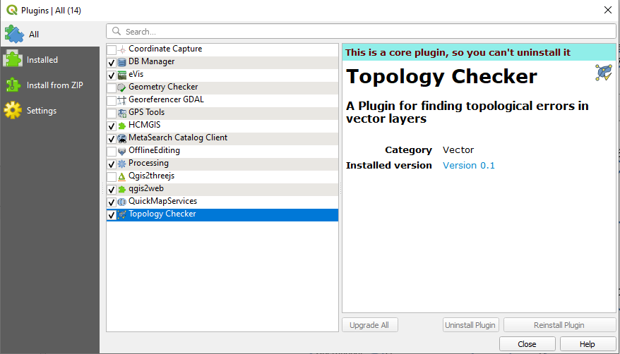
Figure 34 - Activating Topology Checker from Plugins
- Click on the Topology Checker iconto open create topology checker panel window.
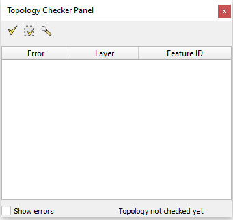
Figure 35 - Topology Checker Panel
From left to right the tools are:
- Validate
- Validate All
- Configure
- Click on Configure and select the layer for creating topology.
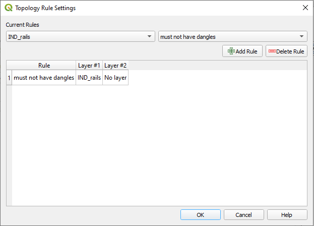
Figure 36 – Topology Rule Setting Window
- Select the layer and assign the rule and click on the Add Rule button, Click OK.
- Click on validate all from topology checker panel window to see errors.

Figure 37 - QGIS showing topology errors
- Once the errors are highlighted use Advance Digitizing toolbar to rectify the errors.
- Depends upon the layer features topology rules are available and they are as follows (feature wise);
For point layers:
- Must be covered by: Here you can choose a vector layer from your project. Points that aren’t covered by the given vector layer occur in the ‘Error’ field.
- Must be covered by endpoints of: Here you can choose a line layer from your project.
- Must be inside: Here you can choose a polygon layer from your project. The points must be inside a polygon. Otherwise, QGIS writes an ‘Error’ for the point.
- Must not have duplicates: Whenever a point is represented twice or more, it will occur in the ‘Error’ field.
- Must not have invalid geometries: Checks whether the geometries are valid.
- Must not have multi-part-geometries: All multi-part points are written into the ‘Error’ field.
For line layers:
- End points must be covered by: Here you can select a point layer from your project.
- Must not have dangles: This will show the overshoots in the line layer.
- Must not have duplicates: Whenever a line feature is represented twice or more, it will occur in the ‘Error’ field.
- Must not have invalid geometries: Checks whether the geometries are valid.
- Must not have multi-part geometries: Sometimes, a geometry is actually a collection of simple (single-part) geometries. Such a geometry is called multi-part geometry. If it contains just one type of simple geometry, we call it multi-point, multi-linestring or multi-polygon. All multi-part lines are written into the ‘Error’ field.
- Must not have pseudos: A line geometry’s endpoint should be connected to the endpoints of two other geometries. If the endpoint is connected to only one other geometry’s endpoint, the endpoint is called a pseudo node.
For polygon layers:
- Must contain: Polygon layer must contain at least one-point geometry from the second layer.
- Must not have duplicates: Polygons from the same layer must not have identical geometries. Whenever a polygon feature is represented twice or more it will occur in the ‘Error’ field.
- Must not have gaps: Adjacent polygons should not form gaps between them. Administrative boundaries could be mentioned as an example (US state polygons do not have any gaps between them…).
- Must not have invalid geometries: Checks whether the geometries are valid. Some of the rules that define a valid geometry are:
- Polygon rings must close.
- Rings that define holes should be inside rings that define exterior boundaries.
- Rings may not self-intersect (they may neither touch nor cross one another).
- Rings may not touch other rings, except at a point.
- Must not have multi-part geometries: Sometimes, a geometry is actually a collection of simple (single-part) geometries. Such a geometry is called multi-part geometry. If it contains just one type of simple geometry, we call it multi-point, multi-linestring or multi-polygon. For example, a country consisting of multiple islands can be represented as a multi-polygon.
- Must not overlap: Adjacent polygons should not share common area.
Comments
Post a Comment