Exercise – 15 / How to Create Topology in QGIS
Topology Creation
Topology describes the relationships between points, lines and polygons that represent the features of a geographic region. With the Topology Checker plugin, you can look over your vector files and check the topology with several topology rules. These rules check with spatial relations whether your features ‘Equal’, ‘Contain’, ‘Cover’, are ‘CoveredBy’, ‘Cross’, are ‘Disjoint’, ‘Intersect’, ‘Overlap’, ‘Touch’ or are ‘Within’ each other. It depends on your individual questions which topology rules you apply to your vector data (e.g., normally you won’t accept overshoots in line layers, but if they depict dead-end streets you won’t remove them from your vector layer).
QGIS has a built-in topological editing feature, which is great for creating new features without errors. But existing data errors and user-induced errors are hard to find. This plugin helps you find such errors through a list of rules.
It is very simple to create topology rules with the Topology Checker plugin.
- Before creating Topology choose Plugins→Manage and Install Plugins→Topology Checker.
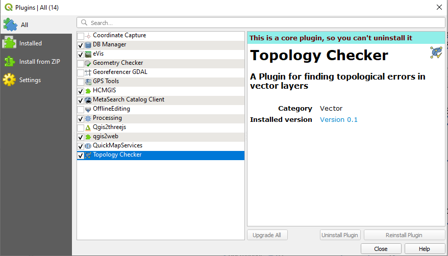
Figure 34 - Activating Topology Checker from Plugins
- Click on the Topology Checker iconto open create topology checker panel window.
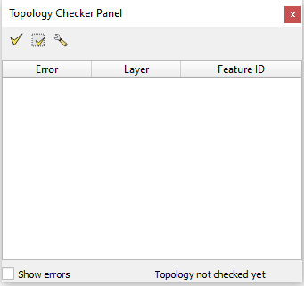
Figure 35 - Topology Checker Panel
From left to right the tools are:
- Validate
- Validate All
- Configure
- Click on Configure and select the layer for creating topology.
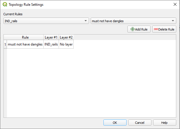
Figure 36 – Topology Rule Setting Window
- Select the layer and assign the rule and click on the Add Rule button, Click OK.
- Click on validate all from topology checker panel window to see errors.

Figure 37 - QGIS showing topology errors
- Once the errors are highlighted use Advance Digitizing toolbar to rectify the errors.
- Depends upon the layer features topology rules are available and they are as follows (feature wise);
For point layers:
- Must be covered by: Here you can choose a vector layer from your project. Points that aren’t covered by the given vector layer occur in the ‘Error’ field.
- Must be covered by endpoints of: Here you can choose a line layer from your project.
- Must be inside: Here you can choose a polygon layer from your project. The points must be inside a polygon. Otherwise, QGIS writes an ‘Error’ for the point.
- Must not have duplicates: Whenever a point is represented twice or more, it will occur in the ‘Error’ field.
- Must not have invalid geometries: Checks whether the geometries are valid.
- Must not have multi-part-geometries: All multi-part points are written into the ‘Error’ field.
For line layers:
- End points must be covered by: Here you can select a point layer from your project.
- Must not have dangles: This will show the overshoots in the line layer.
- Must not have duplicates: Whenever a line feature is represented twice or more, it will occur in the ‘Error’ field.
- Must not have invalid geometries: Checks whether the geometries are valid.
- Must not have multi-part geometries: Sometimes, a geometry is actually a collection of simple (single-part) geometries. Such a geometry is called multi-part geometry. If it contains just one type of simple geometry, we call it multi-point, multi-linestring or multi-polygon. All multi-part lines are written into the ‘Error’ field.
- Must not have pseudos: A line geometry’s endpoint should be connected to the endpoints of two other geometries. If the endpoint is connected to only one other geometry’s endpoint, the endpoint is called a pseudo node.
For polygon layers:
- Must contain: Polygon layer must contain at least one-point geometry from the second layer.
- Must not have duplicates: Polygons from the same layer must not have identical geometries. Whenever a polygon feature is represented twice or more it will occur in the ‘Error’ field.
- Must not have gaps: Adjacent polygons should not form gaps between them. Administrative boundaries could be mentioned as an example (US state polygons do not have any gaps between them…).
- Must not have invalid geometries: Checks whether the geometries are valid. Some of the rules that define a valid geometry are:
- Polygon rings must close.
- Rings that define holes should be inside rings that define exterior boundaries.
- Rings may not self-intersect (they may neither touch nor cross one another).
- Rings may not touch other rings, except at a point.
- Must not have multi-part geometries: Sometimes, a geometry is actually a collection of simple (single-part) geometries. Such a geometry is called multi-part geometry. If it contains just one type of simple geometry, we call it multi-point, multi-linestring or multi-polygon. For example, a country consisting of multiple islands can be represented as a multi-polygon.
- Must not overlap: Adjacent polygons should not share common area.
Comments
Post a Comment